Sensors
In the context of this device and documentation, a sensor refers to a 1-Wire hardware sensor connected to the device, as well as its digital representation.
The egnite 310 supports connecting up to 10 1-Wire sensors.
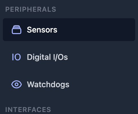
To configure the sensors connected to the device, please navigate to Sensors from the main menu in the Peripherals section.
The Sensors main page presents an overview table, where each row represents one sensor.
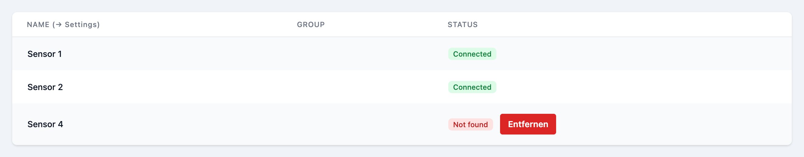
To navigate to the configuration page for a specific sensor, click on the corresponding row.
Adding and removing new sensors
Hardware
Connect the sensor to the 1-Wire bus.
Configuration
Click the button on the top right of the Sensors main page.
The newly connected sensor should appear as an additional row in the overview table.
To configure it, follow the instructions in section Configuring a sensor
Removing a sensor
To remove a sensor, detach the sensor physically. After that either click the Button or reboot the device.
When you return to the list of sensors, a Button should be visible in the respective row in the overview table. Click on it to remove the sensor from the list.
Configuring a sensor
In the sensors overview table, click on the row of the sensor you would like to configure.
This will open the detail configuration page, as shown below.
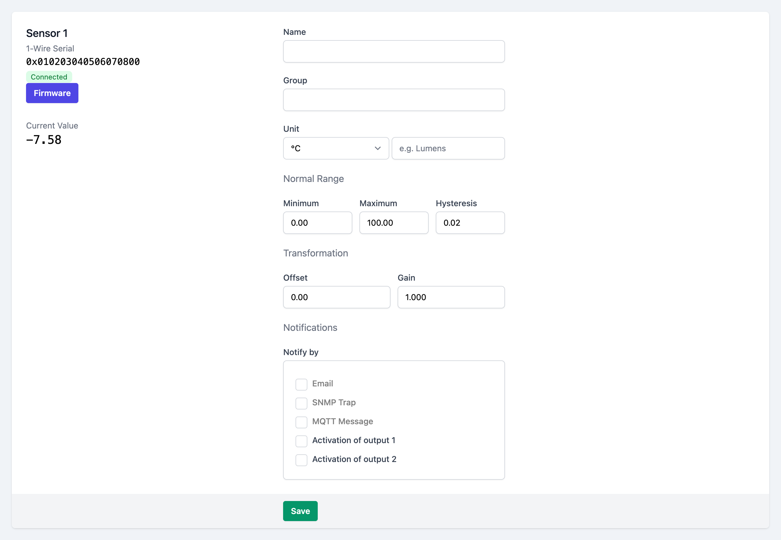
Name
Choose a descriptive name for the sensor.
While not relevant to the functionality, this name will be displayed on several locations of the web interface.
If you leave this field blank, a default name will be displayed instead.
Group
Optionally enter a string as the name for the group, this peripheral should belong to.
If you use the same group name for other peripherals (sensors, digital I/Os, watchdogs), those can be shown and filtered by their group on the dashboard.
Unit
Choose a measurement unit from the dropdown, that suits the sensor.
If your desired unit is not available in the dropdown, choose Custom and enter a descriptive custom unit string in the input field next to the dropdown.
For Kelvin and Fahrenheit, the value will be automatically converted from Celsius.
Normal Range
The normal range determines what should be considered acceptable sensor values.
-
Minimum: If the sensor value gets lower than the provided Minimum threshold, the sensor is considered in a value too low state, which is displayed on the dashboard and can trigger warning notifications (see below).
-
Maximum: If the sensor value gets higher than the provided Maximum threshold, the sensor is considered in a value too high state, which is displayed on the dashboard and can trigger warning notifications (see below).
-
Hysteresis: TODO
Transformation
This specifies a linear transformation, which gets continuously applied to the current sensor value, where
- Offset is a number that gets added to the value
- Gain is a number that gets multiplied to the value.
Notifications
When the current sensor value leaves or reenters the normal range (see above), the device can emit notifications to make the user aware.
Check one or multiple of the checkboxes, which stand for the channel(s), over which the notifications get sent. Multiple channels can be activated simultaneously.
The device sends an email.
The exact text of the emails can be customized by supplying or editing a template on the email configuration page.
Email Configuration page- SNMP Trap
The device sends a SNMP trap.
SNMP Configuration page- MQTT Message
The device sends a MQTT message.
MQTT Configuration page- Activation of output 1
- The device activates digital output 1.
- Activation of output 2
- The device activates digital output 2.
Please note, that for
- Email (Configuration page)
- SNMP Trap (Configuration page)
- MQTT Message (Configuration page)
the respective interfaces have to be configured and enabled through their configuration pages.
Also refer to the Notifications docs page.
Box2Box actions
Similar to notifications, when the Box2Box Feature is enabled, the device can control an digital output on another device, when an events occurs with the peripheral.
The corresponding checkboxes are only visible, after the Box2Box feature has been enabled.
// TODO SCREEN
Check one or multiple of the checkboxes, which stand for the output(s), of the controlled device. Multiple outputs can be controlled simultaneously.
Save the configuration
After filling in the form, click on at the bottom of the page, to persist the configuration.