Chapter 3: Initial Setup
Before the Initial Setup
Before beginning, check that you have received all the parts listed in Chapter 2. If anything is missing, contact your dealer.
If the device’s temperature differs significantly from room temperature, allow it to acclimatize for about two hours before connecting it to power.
We recommend performing the initial setup at your desk before installing Querx at its final location.
You will need:
- A PC with a current web browser
- A power supply
- Either the included USB power adapter
- Or any standard USB charger
- Alternatively, most PC USB ports can power the device
- An Ethernet cable and a free Ethernet port connected to the same network as your PC
- Alternatively: You may connect Querx directly to your PC via Ethernet
- (For WLAN models)
- WiFi connection can be set up later
- WPS connection is also supported
Network Connection
Connect Querx to your network or directly to your PC using an Ethernet cable.
This step is required even for WLAN models, so you can enter your WiFi access data later.
WLAN models may also be connected using WPS, but a wired first-time setup is still recommended.
Power Supply
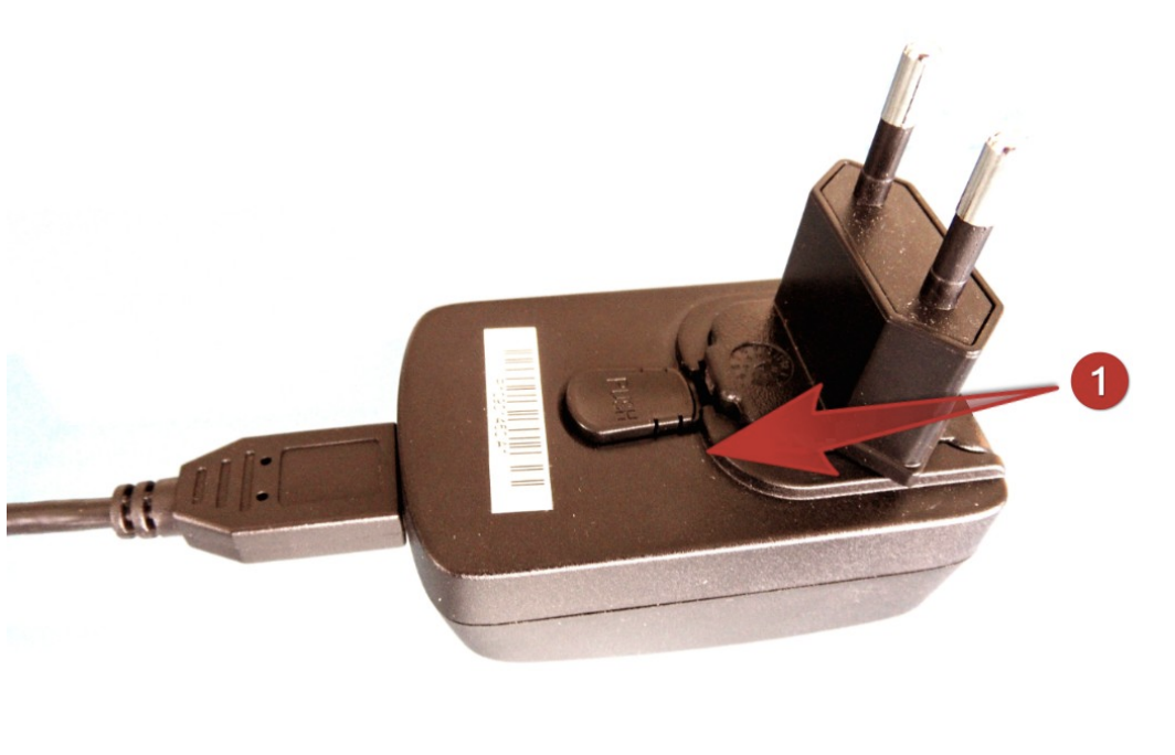
Connect Querx to the power supply:
- Use the supplied USB power adapter
- Or use any common USB charger
- Or power the device directly from your PC’s USB port
After powering the device, the status LED will light up during boot.
Never use the device with a defective power adapter! Risk of death from electrical shock!
Network Configuration
Once powered and connected via Ethernet, Querx will attempt to obtain a dynamic IP address (DHCP).
If your network provides DHCP:
- Querx will automatically appear in the DHCP client list of your router or managed switch
- You can now proceed to access the web interface
If your network does not assign IP addresses automatically:
- See Chapter 9: Network Configuration for detailed instructions on static IP configuration
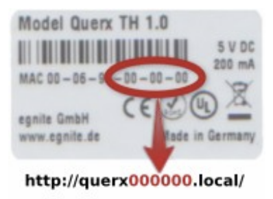
Accessing the Web Interface
To access Querx:
- Open a web browser
- Enter the assigned IP address into the address bar
- The Querx web interface will load
- The default configuration does not require a password
If the device cannot be reached:
- Ensure the PC and Querx are on the same network segment
- Alternatively, connect Querx directly to your PC and configure a temporary IP on the PC
- Refer to Network Configuration if necessary
Installing the Sensor
Most Querx models come with a test sensor to simplify initial setup.
This test sensor is not meant for long-term use.
For PT models (Pt100 / Pt1000):
- Various high-precision sensors with different construction types and tolerances are available from many manufacturers
Let the device acclimatize before taking real measurements.
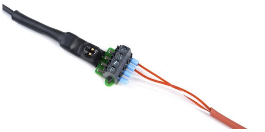
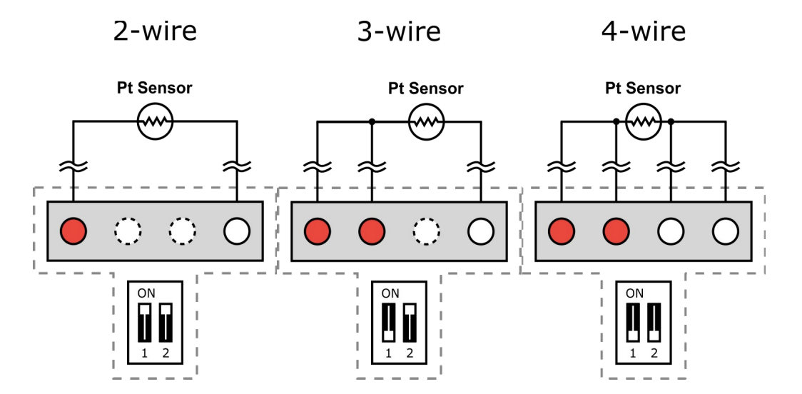
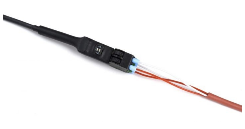
Connecting Pt100- or Pt1000-Sensors
PT models use a temperature sensor that may be connected using 2-wire, 3-wire, or 4-wire configurations.
The correct wiring method must be selected using the DIP switches above the wire terminals.
Two versions of terminal types exist:
- Screw terminals (newer models)
- Spring-loaded terminals (older models)
The manual includes wiring illustrations — insert your own image assets later.
Connecting a Sensor to Screw Terminals
You will need:
- A fine-tip tool (small screwdriver or tweezers)
- A flat-head screwdriver
- (Optional) a magnifying glass
Steps:
- Determine the required DIP switch position for your sensor (2-wire / 3-wire / 4-wire)
- Set the DIP switches using a fine tool
- Loosen the terminal screws (turn counter-clockwise)
- Insert each wire into the appropriate terminal
- Tighten the screws (turn clockwise)
- Gently pull the cable to verify secure connection
Connecting a Sensor to Spring-Loaded Terminals
You will need:
- A fine-tip tool
- A ballpoint pen
- (Optional) a magnifying glass
Steps:
- Identify the correct DIP switch positions for your sensor type
- Set the DIP switches accordingly
- Press the spring fixture with the ballpoint pen
- Insert the cable core into the terminal
- Release the spring fixture
- Lightly pull the cable to test the connection
To remove the cable:
- Press the spring fixture again and pull the wire out
At this point, you have completed the Initial Setup.
For next steps:
- Proceed to Basic Settings (Chapter 4)
- For WLAN models, continue with Network Configuration (Chapter 9)
- For sensor configuration, see Chapter 12